Remote monitor your Davis Anemometer with RMS
If you need to know how fast the wind is blowing, an anemometer is the device you need. An
anemometer is a meterorological device that calculates the speed of wind. Anemometers range
in size and price. There are two main types of anemometers, cup style and windmill style.
Other types of anemometers that are less common include Hot-wire style, Laser Doppler
style, and Sonic style. Most anemometers come with some kind of gauge or LCD readout that
displays the wind speed. But what if you want to monitor the wind speed remotely over an
Internet connection? RMS to the rescue!
This project makes use of the GPIO pins on the RMS-200 board
to count the pulses from the anemometer. An RMS-200
voltmeter is used to measure the wind direction. We chose the popular Davis model 7911 cup
style anemometer because it is inexpensive and fairly accurate.
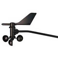
The anemometer kit includes bolts and brackets to fasten the anemometer to a pole or
building. The anemometer comes with 40 feet of 4-wire cable that has a common phone (RJ-11)
connector at the end. A surface mount modular jack was purchased so that the anemometer
cable could easily plug in without splicing into the anemometer cable.
Wind Speed
Theory of operation: There is a magnet in the wind cup assembly and a reed switch in
the head assembly. When the wind cup magnet is over the reed switch, the switch closes
causing the GPIO line on the RMS-200 board to be pulled low. When the magnet passes the
reed switch, the switch opens again causing the GPIO line to go high again. The RMS-200
counts these high to low transitions and writes the pulse count to a file approximately
every 2.25 seconds. The pulse count is the wind speed in MPH.
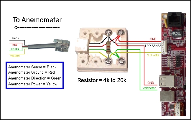
Below is a wiring diagram illustrating how the anemometer is hooked up to the RMS-200
board.
NOTE: A pull up resistor must be used to pull the RMS-200 GPIO pin high. A resistor
value of 4k to 20k can be used. Use the higher resistance value when the wiring to the
anemometer is short, and the lower value when the wiring is long or subject to leakage or
noise.
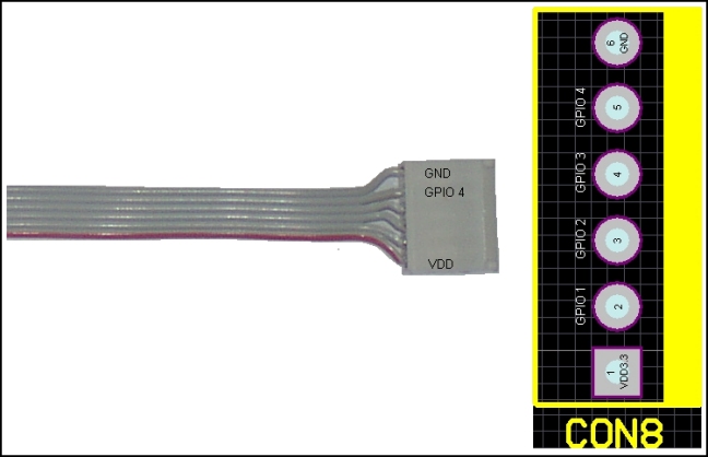
Below is the pin-out of the GPIO port (CON8) on the RMS-200 board. A six pin connector with
ribbon cable was used to interface the RMS-200 board to the modular jack. Only three wires
are used from the ribbon cable, VDD3.3, GND, and GPIO4.
Wind Direction
Theory of operation: The wind vane or rudder attaches to a shaft on the anemometer
head. The anemometer shaft turns a potentiometer inside the head. The potentiometer
produces a voltage between 0 and 3.2 that varies linearly with azimuth. The voltage is
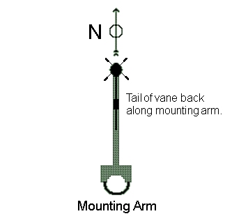
transmitted over 2 wires back to one of the RMS-200 voltmeters. The diagram below shows the
recommended mounting, with the wind vane arm pointing North out from the mast. Before
attaching the vane or rudder, turn the shaft so that the voltage reading is 0 volts, then
attach the vane as shown below.
Software Overview
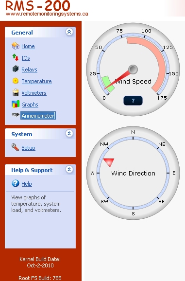
Below is a screen shot of the RMS-200 Davis 7911 anemometer interface. Two gauges show both
wind speed and direction.
The download zip file below contains all of the files needed to display the gauges. Simply
download the files and extract them to your computer. With FTP, upload the files to the
RMS-200 board at /data/custom/. Go to the RMS-200 setup area and add a custom device. In
the "path to custom file" box, enter: custom/anemometer.php and click the OK button. An
anemometer icon will be displayed in the left navbar as shown above. Edit the aserver.php
file to set which voltmeter is used for the wind direction.
Make the anemometer daemon executable by typing on the command line: chmod 755
/data/custom/anemometerd
Start the anemometer daemon (anemometerd gpio_number). To get usage info on the anemometer
daemon, run it without arguments. When the anemometer daemon is running it will create the
wind speed file in /var/rmsdata/a-count.
 Anemometer files
This concludes the anemometer GPIO project. We can now monitor our wind speed and direction
from the comfort of home or at the office with the RMS-200 remote site monitoring
board.
Our Story
EtherTek Circuits started its business in 2001. Ever since we have provided remote monitoring and control solutions for Remote Tower Sites, the Oil & Gas industry, Telemetry systems for Agriculture, Municipalities, Mines, Solar Farms, Hydro Plants, and the Military.


