Windows Client
The Windows Client program is used to read data from the
USBisoVM voltage monitor board. The client program stores all of the default variables and
board settings in a database "USBisoVM.mdb". The database is located in the installation
folder. An installer is provided. Follow the examples below to have the executable, dll,
and database installed on your computer.
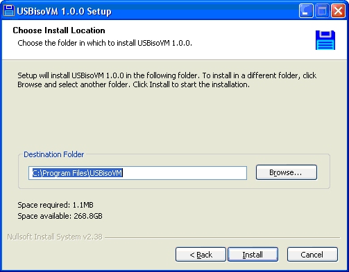
Software Installation
Using The Windows Client
When starting the client program for the first time, it looks to see if a board has
previously been connected. If not, the add device dialog box pops up. This list is
automatically populated with however many USBisoVMs that are found to be connected to the
host. Each USBisoVM is programmed with a unique identifier. The "Refresh" button will
re-poll the USB port and find any units plugged in. NOTE: Windows Vista and
Windows 7 users must run the client program as Administrator.
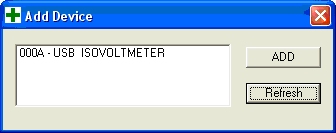
Select the desired unit and hit the "ADD" button. The selected device has now been added to
the database. The main program will now appear. If the "Add Device" dialog box is closed
without selecting a device, the main program will still open, however, a device will still
need to be added in order to poll information.
To add another device, click the "ADD Device" button. If there are multiple USBisoVMs in
the list, you may make one default (shows up in the list box first) by selecting the "Set
Default" button. If at any time you wish to remove a device, have the desired device
selected in the drop-down menu and click the "Delete Device" button.
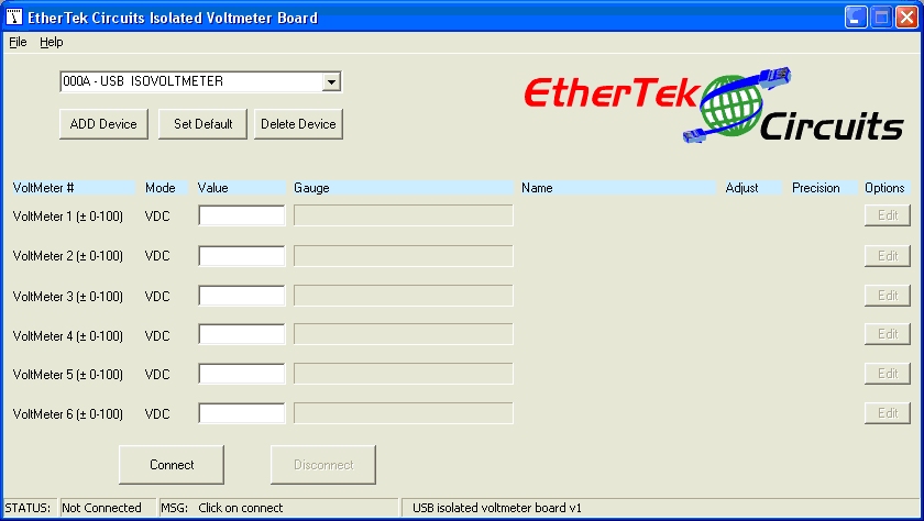
To start polling information, select the desired device from the drop-down menu and click
on "Connect"
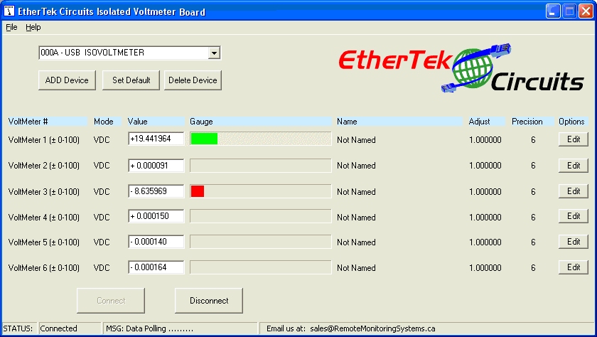
The program will connect to the USB isolated Voltmeter board selected and display the
voltage per voltmeter onto the main screen. The value is in decimal under the "Value"
column as well as displayed in the gauge. If the voltage is positive, the gauge will appear
green, if negative, it will appear red.
Note 1: Voltmeters that have nothing hooked up to them so that the positive and
negative inputs are floating may read spurious positive and negative voltage readings, this
is normal. You may dampen the voltage reading by sacrificing accuracy using the precision
box. Use a number between 2 and 6 to increase or decrease the decimal place.
Note 2: Due to variations in components and the manufacturing process, voltmeter
readings may differ slightly from each other and from your hand held DVM. Use the
adjustment box to fine tune the voltmeter to display the expected value.
A few other main features are displayed on the main page such as:
Name - Displays a name given to the voltmeter. 20 Characters MAX. In this screen, if the
mouse hovers over the name, the notes on how the voltmeter is hooked up will appear.
Mode - The voltmeter mode can be changed from "VDC" or "ADC"
Adjust - The adjustment value. The adjustment value is multiplied against the voltage
reading and is displayed in the "Value" column.
Precision - The desired precision to be displayed, this value can be 0-6. Default value is
6 decimal places.
If any of these settings needs to be changed, or if more advanced features are needed,
click on the "Edit" button. Each edit button is only applicable for the voltmeter of
whichever row it is in. In the example below, the "Edit" button for Voltmeter 3 is
clicked.
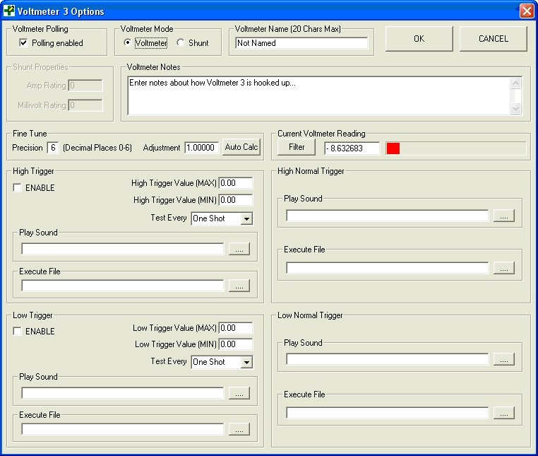
The Voltmeter Options Dialog pops up. Each of the features are:
"Voltmeter Polling" - When this is selected, data will be requested from the USBisoVM.
However, if faster reading times are desired, then disabling some of the unused voltmeters
can achieve this. When disabled, the value appears as "DISABLED".
"Voltmeter Mode" - Select the desired mode for the voltmeter to be in. Voltmeter mode is
default. The shunt mode will calculate the current based upon the shunt properties
entered.
"Voltmeter Name" - This is where the Name of the voltmeter can be entered and edited. This
will also appear on the main screen.
"Shunt Properties" - This section is enabled once shunt mode is selected. Enter in the
properties of the shunt being used. A typical value would be (Amp Rating = 5; Millivolt
Reading = 50) for a 5A/50mV shunt.
"Voltmeter Notes" - Enter in notes for reference on how the voltmeter is used.
"Fine Tune" - There are 2 ways to fine tune the voltage reading. "Precision" and
"Adjustment". Precision will alter to how many decimal places the voltage will show. This
can vary from 0 to 6 decimal places. Adjustment is a multiplication factor against the
voltage reading. This would most commonly be used for calibration or when reading a
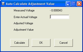
stepped-down voltage. As an aide, the "Auto Calc" button will calculate the adjustment
value needed to achieve the desired voltage reading. The desired voltage reading is "Actual
Voltage".
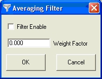
"Current Voltmeter Reading" - The real-time reading of the selected voltmeter. If desired,
the averaging filter can be enabled by clicking on the "filter" button. The averaging
filter will settle the voltage bounce readings. The weight factor should be between 0 and
1. The larger the number, the faster the answer is obtained. The lower the number, less
bounce occurs. A good default is 0.05 if the precision is set to 6.
C = w(C-P)+P
C = Current voltage reading
P = Previous voltage reading
w = Weight factor (as determined by value entered into text box)
The next section are the Triggers. These enable some control with the program. The
available controls are; playing a sound (like an alarm) or executing a file (ie. A script
to store the information). To use the triggers, the enable box must be checked.
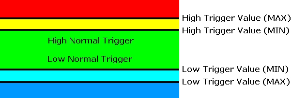
When a voltage is within a trigger range (as shown by the different colour bands), the
action will only execute as often as specified by the "Test Every" pull down list.
If a voltage is in the green (Normal Range), and moves past the High trigger value (MIN)
into the yellow, no actions occur. Only if the voltage moves into the red range (past High
Trigger Value (MAX)) will the action occur. If the voltage flutters into the yellow and
back into the red, this does not reset any triggers. High Trigger condition range only
exits once the voltage goes back into the green where it will execute the "High Normal
Trigger" action only once. The same theory applies to the Low Trigger values.
Logging
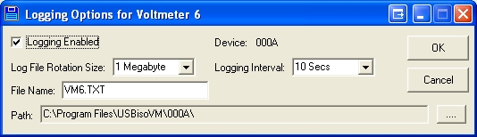
To log voltages to a file for later analysis choose "Logging" from the main pull down menu.
Logging options can be set up for each voltmeter. Each voltmeter has its own log file. In
the picture above, the maximum file size is set to 1 megabyte (1048576 bytes) with readings
taken every 10 seconds. When the log file size goes over the set limit of 1 megabyte, the
log file is deleted and a new log file is started. It is up to the user to determine how
much hard drive space is available for log files and to do something with them before they
are deleted. Below is an example of log file readings taken from a voltmeter log file. Each
field in the log file: date, time, and voltage reading is separated with a semicolon.
06 May 2010;04:05:23 PM;- 2.357256
06 May 2010;04:05:33 PM;- 2.357183
06 May 2010;04:05:43 PM;- 2.357183
Each line in the log file uses 36 bytes (including the carriage return, and linefeed).
A one megabyte log file can contain over 29,000 entries.
Log files as large as 35 megabytes (36700160 bytes) can be chosen.
Graphs
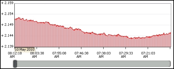
To display your log files in a graph, choose "Graphs" from the main pull down menu. To zoom
in, drag the mouse over the graph. To zoom out, click the left mouse button over top of the
graph.
Our Story
EtherTek Circuits started its business in 2001. Ever since we have provided remote monitoring and control solutions for Remote Tower Sites, the Oil & Gas industry, Telemetry systems for Agriculture, Municipalities, Mines, Solar Farms, Hydro Plants, and the Military.


