|
|
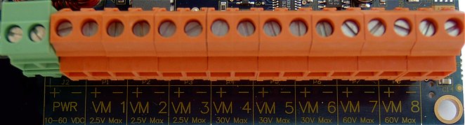
Voltmeter 1, 2, and 3 have a max range of 0 to +2.5 vdc. In this mode the volmeter has over 4 million steps. This is perfect for calculating amperage by measuring voltage drop across a current shunt. Voltmeters 4, 5, and 6 are general purpose voltmeters for measuring dc voltage from 0 to +30 vdc. Voltmeters 7 and 8 are general purpose voltmeters for measuring dc voltage from 0 to +60 vdc.
Note 1: Voltmeters that have nothing hooked up to them so that the positive and negative inputs are floating may read spurious positive and negative voltage readings, this is normal. You may dampen the voltage reading by sacrificing accuracy using the precision box. Use a number between 2 and 6 to increase or decrease the decimal place.
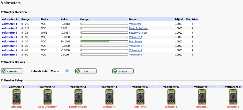
Below is a screen shot of the SRMS voltmeter overview page. This page shows at a glance all voltmeter readings and provides a gateway for more voltmeter options.
Here you can enter setup information like a name and notes for this voltmeter. The precision box is used to set how many decimal places to display, valid choices are between 2 and 6. The adjustment box is used to fine tune the voltmeter. The �Suppress Trigger Actions on Boot� check box is used to stop actions from happening when the SRMS board is warm or cold started. Each voltmeter has a High, Normal, and Low trigger range. Each trigger range has a maximum and minimum value. The range in between the maximum and minimum value acts like a dead band area. Triggers can be set to fire alerts or scripts when the voltage is either too high or too low. The High Trigger is used when the voltage rises above the High Trigger maximum value. The Normal Trigger is used when the voltage falls below the High Trigger minimum value. The �Test Every� box is used to select how often the condition should be tested and acted upon. Each voltmeter trigger can also execute a custom file stored on the SRMS board.
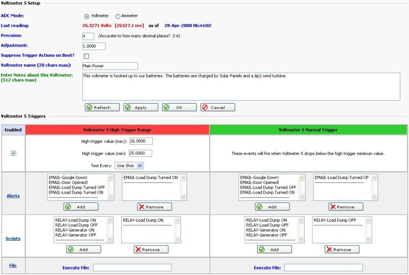
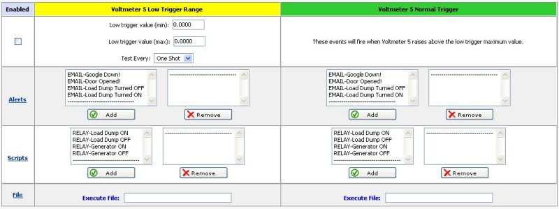
Below is the Low Trigger interface. The Low Trigger is used when the voltage falls below the Low Trigger maximum value. The Normal Trigger is used when the voltage rises above the Low Trigger minimum value.
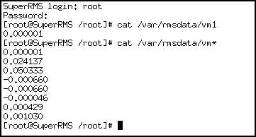
Below is an example of reading the voltmeters on the command line. Note: the voltmeter readings are stored in files. Voltmeter 1's storage file is called vm1. Voltmeter 2's storage file is called vm2 etc.
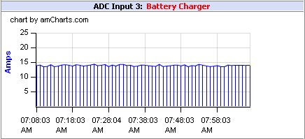
Each voltmeter has a corresponding graph associated with it. By default, graphs show the last hour of data, but can be set in the Cron Scheduler to show any time interval. Below is a graph showing amps.
If you are managing a remote battery powered site, knowing your battery voltage is vital. It is also a key thing to know how much charging you are putting back into your batteries. Using a common shunt, it is possible to obtain a millivolt reading that relates to an amperage reading. The 0 to + 2.5 voltmeters on the SRMS board are perfect for this as they are very sensitive and can easily read millivolt readings.
Shunts are defined as a resistive load through which electricity is diverted. Often the resistance of a shunt is known precisely and is used to determine amperage by measuring the voltage across it and using Ohm's law (I = V/R). It also allows high current measurements with low-current equipment. Some popular shunts are 50mv/50amp and 100mv/100amp. The relationship between the millivolt reading and the current going through the shunt makes figuring out the amperage easy. For example, in the case of the 50mv/50amp shunt: if you had 50 amps of charging going through the shunt then the millivolt reading would be 50mv. If you had 25 amps of charging going through the shunt then the millivolt reading would be 25mv etc etc. When measuring current over 100 amps, continuous operating current should not exceed 2/3 ammeter shunt rating. To ensure proper operation, the shunt temperature is in no way to exceed 145�C, as a permanent change in resistance will occur. For example, if continuous current for an application is 500 amps, the ammeter shunt rating should be no less than 750 amps. This applies to both 50 and 100 millivolt current drop shunts.
To learn more about shunts and how much they cost, please visit www.deltecco.com
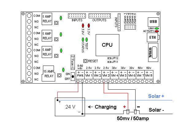
Below is an example diagram of how to use SRMS with a shunt to measure charging from a solar panel array. The positive solar panel lead is connected to the battery positive terminal. The negative solar panel lead is routed to the negative battery terminal by way of a 50 millivolt 50 amp current shunt. From one side of the shunt there is a sense wire run to the negative input on VM3. From the other side of the shunt there is a sense wire run to the positive input on VM3.
Note1: Only use the negative lead when connecting current shunts to any power source.
Note2: Always confirm the proper polarity of the shunt sense wires using a hand held volt meter before attaching them to the SRMS board.
Note3: If you are using shunts to monitor charging, DO NOT use shunts to monitor current draw with the same SRMS board. Doing so may damage the ADC circuit on the SRMS board.
Below is a screen shot of how to setup Voltmeter 3 to act as an ammeter to show how much charging is going into the batteries from solar panels. First, put Voltmeter 3 into ammeter mode and click Apply. Next, enter valid shunt values (amperage rating, millivolt value), enter name and notes and then click Apply or click Ok.
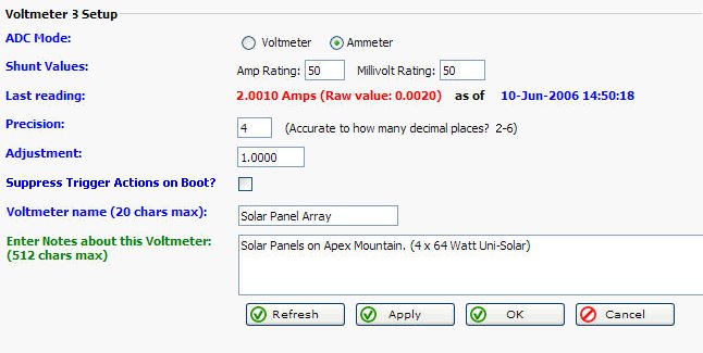
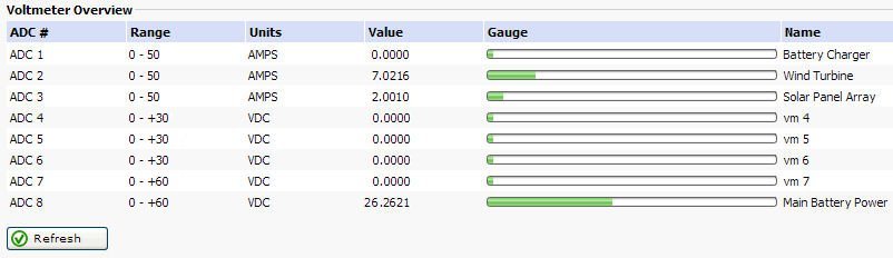
If everything is hooked up correctly you should be able to see how much amperage is being put into your batteries. In the screenshot below the 24 volt main battery bank is being charged by both solar and wind. This technique can be used to measure DC current being put into your batteries by solar panels, a wind generator, or a battery charger. SRMS can monitor your voltage and amperage remotely and alert you to dangerous battery conditions.
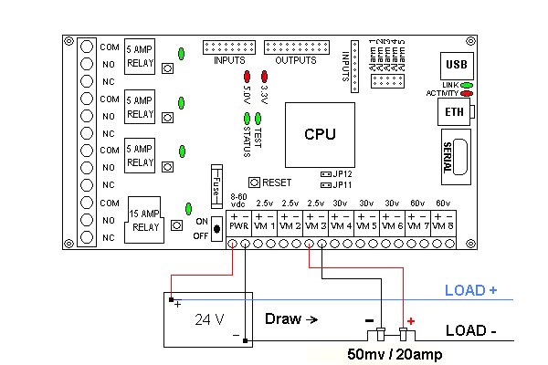
Below is an example of how to use SRMS with a shunt to measure current draw from your equipment. The positive load wire is connected to the battery positive terminal. The negative wire is routed to the negative battery terminal by way of a 50 millivolt 20 amp current shunt. From one side of the shunt there is a sense wire run to the negative input on VM3. From the other side of the shunt there is a sense wire run to the positive input on VM3.
Note1: Only use the negative lead when connecting current shunts to any power source.
Note2: Always confirm the proper polarity of the shunt sense wires using a hand held volt meter before attaching them to the SRMS board.
Note3: If you are using shunts to monitor current draw, DO NOT use shunts to monitor charging with the same SRMS board. Doing so may damage the ADC circuit on the SRMS board.