 |
|
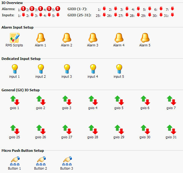
Below is a screen shot of the SRMS I/O overview page. Here you can choose which of the boards Alarm or I/O pins to control. SRMS has 5 dedicated Alarm Pins that have a corresponding LED. Use them with common door contacts to monitor entry points. SRMS has an extra 5 dedicated inputs for general purpose use. SRMS also has 14 general purpose pins that can be set as Inputs or Outputs. These multi purpose I/O pins can be controlled or read from either the web page interface or a command shell. SRMS also has 3 micro push buttons that have special attributes when the SRMS board is booting. After the SRMS board is finished booting these buttons are free for you to use for controlling your devices.
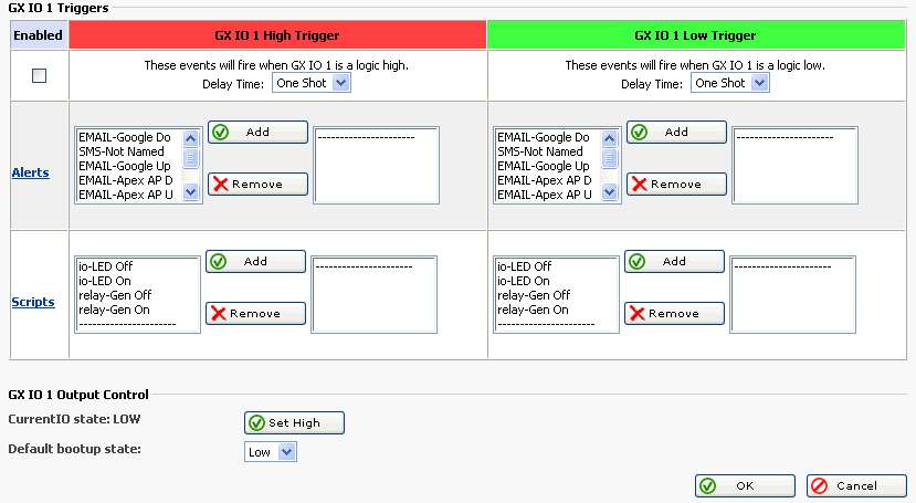
Below is a screen shot of the SRMS I/O setup page for GXIO 1. GXIO pins can be configured to be 5 volt tolerant TTL Inputs or Outputs. Use these pins to control any manner of devices, or sense condition changes and react with alerts or scripts.
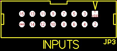
Below is a pinout diagram of JP3 on the SRMS board. GXIO 5v tolerant inputs.
| Note: Pin 1 is VDD (3.3 volts). Pin 2 is GXIO 1 input pin. Pin 3 is GXIO 2 input pin. Pin 4 is GXIO 3 input pin. Pin 5 is GXIO 4 input pin. Pin 6 is GXIO 5 input pin. Pin 7 is GXIO 6 input pin. Pin 8 is GXIO 7 input pin. Pin 9 is GXIO 25 input pin. Pin 10 is GXIO 26 input pin. Pin 11 is GXIO 27 input pin. Pin 12 is GXIO 28 input pin. Pin 13 is GXIO 29 input pin. Pin 14 is GXIO 30 input pin. Pin 15 is GXIO 31 input pin. Pin 16 is GND. |
 |
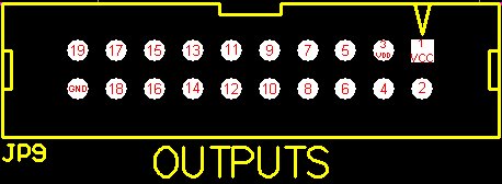
Below is a pinout diagram of JP9 on the SRMS board. GXIO 5v tolerant outputs.
| Note: Pin 1 is VCC (5.0 volts). Pin 2 is No Connect. Pin 3 is VDD (3.3 volts). Pin 4 is No Connect. Pin 5 is No Connect. Pin 6 is GXIO 1 output pin. Pin 7 is GXIO 2 output pin. Pin 8 is GXIO 3 output pin. Pin 9 is GXIO 4 output pin. Pin 10 is GXIO 5 output pin. Pin 11 is GXIO 6 output pin. Pin 12 is GXIO 7 output pin. Pin 13 is GXIO 25 output pin. Pin 14 is GXIO 26 output pin. Pin 15 is GXIO 27 output pin. Pin 16 is GXIO 28 output pin. Pin 17 is GXIO 29 output pin. Pin 18 is GXIO 30 output pin. Pin 19 is GXIO 31 output pin. Pin 20 is GND. |
 |
Below is a pinout diagram of JP2 on the SRMS board. General purpose 5v tolerant inputs.
| Note: Pin 1 is VDD (3.3 volts). Pin 2 is No Connect. Pin 3 is input pin 1. Pin 4 is input pin 2. Pin 5 is input pin 3. Pin 6 is input pin 4. Pin 7 is input pin 5. Pin 8 is GND. |
 |
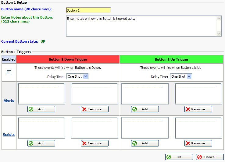
Below is a screen shot of the SRMS Push Button 1 setup page. Use these buttons to manually control devices, or use them for onsite testing of alerts or scripts.
Button 3 Note:
When the SRMS is booting up it first checks to see if Button 3 is being held down. If Button 3 is held down then the 9 pin serial port is set for serial console debug mode. IO is achieved with a NULL modem cable plugged into your pc computer (115200,8,n,1). When the debug console is enabled the serial port cannot be used for normal operation of serial devices like modems etc. To disable serial console debug mode and enable normal operation of the serial com port, simply reboot the SRMS board.
Button 1 Note:
SRMS next checks to see if Button 1 is being held down. If Button 1 is being held down when SRMS is booting up then all of the configuration files are re-written bringing the SRMS unit to a factory default condition.
Button General Note:
When the STATUS LED on the SRMS board starts blinking, the Linux OS has fully booted and normal button operation can commence.