|
|  |
|
Introduction
SRMS Is a unique remote monitoring, data
acquisition, and control device specifically designed for
use with Battery powered Wireless Internet repeater sites, or other AC & DC powered
remote equipment
SRMS Has ultra low power consumption
and won't put a drain on your power source.
SRMS Is powered by DC voltage from 10 to 60 volts.
SRMS Uses embedded Ethernet technology
for internet data acquisition and remote voltage monitoring.
SRMS Uses the LINUX operating system for versatility, stability, and security.
SRMS Gives you the situational
awareness you need to keep your equipment operational and reliable. |
|
|
Possible
Applications
AC or Battery
Powered Microwave / Telephony / Network Equipment
Use SRMS to monitor battery
levels, room temperature, signal strength (RSSI) on radios and more.
SRMS
has 8 onboard voltmeters giving it the ability to measure DC voltage from 0 to +60 volts with 23 bit accuracy.
SRMS
also has 4 power relays giving it the unique ability to turn on/off devices remotely using
an Internet connection. Use the power relays to remote start a generator. SRMS has 5 dedicated input pins used for door alarms or to monitor motion sensors.
SRMS has a full featured serial port, control modems, cell phones, gsm modules, and other devices that use serial communication.
SRMS has a USB port that supports several USB devices concurrently using a USB hub. Control USB cameras, store data on USB flash drives, control USB speakers etc.
SRMS has input and output pins used to control your own custom devices. SRMS can alert you via email or SMS messages when your battery bank is low.
SRMS has ping monitor software that allows you to monitor network devices and alert you to failure and possibly power cycle the device.
Monitor all this information remotely over an Internet connection using an ordinary web browser. SRMS
gives you direct hardware control of fans, lights, computers, cameras, modems, radios, etc... No more guessing what your battery levels are. No more wondering if your signal strengths are at an acceptable
level. No more long drives to reset a fussy radio. Let SRMS do this all remotely via the Internet. The ultimate in remote voltage monitoring.
|
|
|
SRMS
Features
Features:
1) Three 0 to +2.5 vdc Volt Meters. Perfect for measuring voltage drop across current shunts.
2) Three 0 to +30 vdc General Purpose Volt Meters.
3) Two 0 to +60 vdc General Purpose Volt Meters.
4) One onboard temperature sensor 10c +65c.
5) Dual Low noise switching power supplies, SRMS accepts 8-60 vdc input.
6) Three power relays for devices using 1 240v -5 amps AC/DC current.
7) One power relay for devices using 1 240v -15 amps AC/DC current.
8) Power outputs, 5.0vdc and 3.3vdc (500ma each).
9) Serial port for controlling cell phones, modems etc.
10) High performance 10/100 Ethernet connectivity.
11) 100 MHz Etrax Risc processor with MMU, 4 megs Flash, 16 Megs DRAM.
12) Hyper accurate 24 bit Analog to Digital converter with 8 channel mux.
13) Five I2C ports for controlling I2C devices, LCD displays etc.
14) USB port for cameras, wireless clients, extra ethernet etc.
15) Runs real Linux! 2.6.19 kernel.
16) Command line utilities: ping, ftp, email, relays, etc.
17) Flash new firmware over the internet.
18) Hardware Watchdog Reset.
19) Control SRMS via web page, telnet, or ssh.
20) Make your own utilities and scripts to upload.
21) Pluggable connectors for ease of use.
Put
any circuit on the Internet with SRMS!
Custom
built firmware software available upon request. Other hardware and
software modifications available by special order. Please refer to
the contacts at the bottom of this page.
|
|
|
|
Configuration
Setting
up SRMS
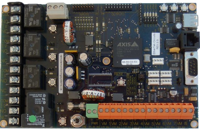
Connect
8 - 60 volts dc power (at least 500 ma) to the power inputs on the terminal block
that is beside the on/off switch (See figure 1) Connect an Ethernet cable
to the rj-45 jack on the SRMS board. Turn the device on with the
on/off switch.
Note1: 12 gauge wires should be used for the power input. Keep the length as short as reasonably possible.
Note2: SRMS units should be mounted inside a steel enclosure that is grounded properly to prevent Electro Magnetic Interference.
Figure 1
SRMS
is powered up, Now what?
We recommend configuring SRMS before deploying it in the field.
Simply plug SRMS into a hub or switch using a standard Ethernet cable or directly into
a computer using a crossover cable.
When SRMS
is turned on it boots the Linux operating system and uses the values stored
in its configuration files to bring up the system. The default values consist of a IP number, username, and password.
The default IP number is 10.10.10.10. The default username is root. The default password is pass.
 |
Note: You may at anytime restore the SRMS device to factory default values by pressing and
holding down the micro push button #1 located near the usb connector and then turning
the RMS device on with the on/off switch. Release the button when the alarm leds start to flash.
When the alarm leds stop flashing, the SRMS unit will reboot and will be ready to configure. |
Give your computer an ip address in the 10.10.10.X class. For instance use 10.10.10.1.
Set your computers Netmask to 255.255.255.0 There is no need to set a Gateway at this time.
Open your favorite web browser and enter 10.10.10.10 into the address bar, press enter or the
go button. You should be presented with a password box like the one below.
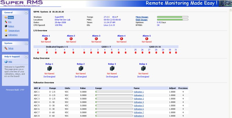
Enter in the default username and password then press the OK button. You will be taken to the
SRMS Home page. This page contains an overview of all of the functionality of the Super RMS board.
In the left side panel, click on the Setup icon. This takes you to the System Setup area
shown below.
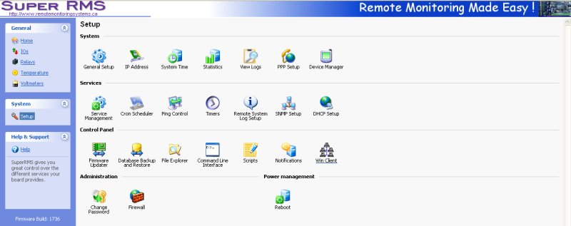
Here you will want to visit the following areas: General Setup , IP Address ,
System Time , Contact Information , and Change Password.
Adjust the Station Name, Location, Domain Name, IP Address, Subnet Mask, Gateway, DNS,
and password you want the device to have. Caution must be taken when configuring
the device, entering incorrect values may cause you to lose connectivity with the
device permanently, forcing the need for a firmware reset.
Once you have SRMS configured properly, it is ready to deploy in the field.
Below are some basic examples of how to install the Super RMS unit.
|
|
|
|
Installation
Basic Installation
Example 1
Measuring
your Battery Bank
To measure
your main battery power supply, run a wire from the positive side of the
battery bank to one of the ADC 30v or 60v positive inputs. Run a second wire
from the negative side of the battery bank to the corresponding ADC 30v or 60v negative
input as shown in Figure 2. Connect SRMS to the internet with
a common Ethernet cable and monitor the voltage level of your battery bank
with a web browser. Note: 12 gauge wires should be used for the voltmeter inputs.
Figure 2
Basic Installation
Example 2
Signal
Strength on Link CX Radios
Radios that have an external RSSI port for checking signal strength can
be monitored with ease. Simply attach the RSSI output from the radio to one of the 30 volt
ADC inputs on the SRMS board (see Figure 3).
Monitor the signal strength of your radios with a web browser and/or have SRMS
alert you by email if the signal falls below a certain threshold.
Figure 3
Basic
Installation Example 3
Turning
Devices ON/OFF
To make any device
remotely resetable, simply cut one of the wires in the power cord of
a device. Attach one side of the cut wire to the COM terminal on one of
the Power Relays. Attach the other side of the cut wire to the NC (normally
closed) terminal on the corresponding Power Relay. Reset your device at
any time using SRMS. Note: in the Normally Closed
configuration, power still flows to your device even when the SRMS device
is turned off. Virtually any 1 to 240 volt AC or DC device can be
turned ON/OFF remotely this way. The three small Power Relays can pass up
to 5 amps each, the larger Power Relay up to 15 amps!. For devices
that should be by default turned off, use the COM and NO (normally open)
configuration. Figure 4 illustrates just one of the many ways you can set
up devices for remote reset.
Figure 4
Basic
Installation Example 4
Using the Alarm pins to monitor door contacts
To give your equipment room some security you can
use widely available common door contacts. These contacts allow current to flow
through them when they are in close proximity with each other. SRMS can
sense when the contacts are together or apart. Program the alarm pins to send an
email, run a custom file, and/or toggle a relay when the door gets opened. The diagram below (figure
5) shows how to use Alarm pin 5 to monitor door contacts.
Note1: the LED5 light is on when the contacts are together. This is the armed position.
Note2: each Alarm pin has a corresponding LED.
Figure 5
|
|
|
|
SRMS
Hardware Screen Shot
|
|
|
MRTG Scripts
available
These real-time MRTG samples are updated every five minutes!
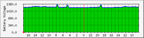
Main Battery Power on Apex Mountain
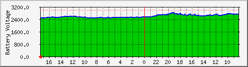
The graph above depicts main battery power at our wireless internet
repeater site on Apex Mountain. Bumps in the graph represent charging from
either solar panels or an Air403 wind turbine. Supplementary power is provided
by a Honda Generator that is remote started with RMS. The 24v battery bank is monitored
by RMS and polled every five minutes. This provides a quick and easy way to
check battery levels at anytime from anywhere a web browser is available!
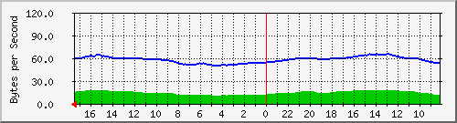
Temperature
Monitor on Apex Mountain
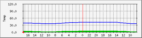
The graph above depicts room temperature at our wireless internet repeater site on Apex Mountain. Dips or bumps in
the graph represent temperature changes. The temperature of our equipment room is monitored
by RMS and polled every five minutes. This provides a quick and easy way to
check temperature at anytime from anywhere a web browser is available!
Main Battery Power on Hedley Mountain
The graph above depicts main battery power at our wireless internet
repeater site on Hedley Mountain. Bumps in the graph represent charging from
either solar panels or an Air403 wind turbine. Supplementary power is provided
by a Honda Generator that is remote started with RMS. The 12v battery bank is monitored
by RMS and polled every five minutes. This provides a quick and easy way to
check battery levels at anytime from anywhere a web browser is available!
Temperature
Monitor on Hedley Mountain
The graph above depicts room temperature at our wireless internet repeater site on Hedley Mountain. Dips or bumps in
the graph represent temperature changes. The temperature of our equipment room is monitored
by RMS and polled every five minutes. This provides a quick and easy way to
check temperature at anytime from anywhere a web browser is available!
|
|

For
further information, technical questions or to purchase equipment please
choose from the following:
Contact:
In Canada & Overseas
EtherTek Circuits
Dan Pattison
Phone (250)295-6794
email: sales(at)remotemonitoringsystems.ca
In the United States
Invictus Networks LLC
Rick Lindahl
Phone: 503-635-2562,
Fax: 503-635-9207
email: rickl(at)invictusnetworks.com
|
|
|
|


