RMS-300v2 - The Super Remote Monitoring System

Click the image below for more information

Remote Voltage Monitoring

Remote Voltage Monitoring at the next level!


RMS-300v2 - Remote Voltage Monitoring board Specs


The information below is here for historical reasons only.


Remote Monitoring Made Easy!

The product below has been discontinued.
Click here for replacement products.


Manufactured by: EtherTek Circuits LTD
RMS
 
Download
F.A.Q.
Specs
Calibration
Graphing
Warranty
Relay Project
About SNMP
About Security
Upgrade
rms
 

Introduction

RMSv1 Is a unique remote data acquisition and control device specifically designed for
use with Battery powered Wireless Internet repeater sites, or other AC & DC powered
remote equipment. 

RMSv1 Has ultra low power consumption and won't put a drain on your power source.

RMSv1 Uses embedded Ethernet technology for internet data acquisition. 

RMSv1 Gives you the situational awareness you need to keep your equipment operational and reliable.

 
RMS
 
Possible Applications

AC or Battery Powered Microwave / Telephony / Network Equipment

Use RMSv1 to monitor battery levels, room temperature, signal strength (RSSI) on radios and more. RMSv1 has 8 onboard volt meters giving it the ability to measure dc voltage from 0 to 60 volts with 12 bit accuracy. RMSv1 also has 3 power relays giving it the  unique ability to turn on/off devices remotely using an Internet connection. RMSv1 has 5 multi purpose digital I/O input pins, use them to monitor motion sensors, door contacts etc. Monitor all this information remotely over an Internet connection using an ordinary web browser or the supplied software utility. RMSv1 gives you direct hardware control of fans, lights, computers, radios, etc... No more guessing what your battery levels are No more wondering if your signal strengths are at an acceptable level.  No more long drives to reset a fussy radio.  Let RMSv1 do this all remotely via the Internet. The ultimate in remote voltage monitoring.

RMS
 
RMSv1 Features

1)    Two 0 - 30 or 0 - 60 dc Volt Meters.
2)    Three 0 - 30 dc Volt Meters.
3)    Three 0 - 5 dc Volt Meters.
4)    One onboard temperature sensor –10c +65c.
5)    Low noise switching power supply, accepting 10-60 vdc input.
6)    Only 75-ma power used at 12 volts.
7)    Two power relays for devices using 1 – 240v -5 amps AC/DC current.
8)    One power relay for devices using 1 – 240v -15 amps AC/DC current.
9)    Five multi purpose I/O pins.
10)  High performance 10 base T Ethernet connectivity.
11)  8 MHz AVR micro controller for the smartest devices.
12)  12 bit Analog to Digital converter with 8 channel mux.
13)  Adjustable constant current generator.
14)  I2C interface for Relay Daughter Board.
15)  SPI interface for on-site firmware upgrades.
16)  Hardware Watchdog Reset.
17)  Remote Management software for Windows ™ operating systems.
18)  View RMSv1 output via web page.
19)  Limited SNMP support.

Put any circuit on the Internet with RMSv1!  Custom built firmware software available upon request.  Other hardware and software modifications available by special order.  Please refer to the contacts at the bottom of this page.

RMS
 
Configuration

Setting up RMSv1

Connect any 10 - 60 volts dc power supply to the power inputs on the terminal block that is beside the on/off switch (See figure 1) Connect a Ethernet cable to the rj-45 jack on the RMSv1 board. Turn the device on with the on/off switch.

Note1: 12 gauge wires should be used for the power input. Keep the length as short as reasonably possible.
Note2: RMSv1 units should be mounted inside a steel enclosure that is grounded properly to prevent Electro Magnetic Interference.


Figure 1


RMSv1 is powered up, Now what?

We recommend configuring RMSv1 before deploying it in the field. Simply plug RMSv1 into a hub or switch using a standard Ethernet cable or directly into a computer using a crossover cable.

When RMSv1 is first turned on it checks to see if it has been previously configured. If it has, RMSv1 will use the settings you have provided. If RMSv1 hasn't been previously configured, it will then use default values stored in the onboard EEPROM. You may at anytime restore the RMSv1 device to factory default values by pressing and holding down the micro push button switch located by the Constant Current Port connector, and then turning the RMSv1 device on with the on/off switch. The default values consist of a Mac Address, IP number, and password. The default Mac Address is 00:00:00:12:34:56. The default IP number is 10.10.10.10. The default password is "public".

Run the supplied RMSv1 software and select from the Connect To:   box 10.10.10.10 and then hit the Auto Add Route button. This adds a route to IP address 10.10.10.10. Next press the Auto Ping button. The RMSv1 device should respond to the pings and be ready for further configuring. Press the Acquire Data Button. The display should be filled with values for Mac address and voltage readings as well as relay settings and temperature. Adjust the Mac Address, IP number and password you want the device to have. Caution must be taken when configuring the device, entering incorrect values may cause you to lose connectivity with the  device permanently, forcing the need for a firmware reset. See the FAQ for more information on setting the Mac Address. Once you have RMSv1 configured properly, it is ready to deploy in the field. Below is some basic examples of how to install the RMSv1 unit.


RMSv1
 
Installation

Basic Installation Example 1

Measuring your Battery Bank

To measure your main battery power supply, run a wire from the positive side of the battery bank to one of the ADC 0-30v positive inputs. Run a second wire from the negative side of the battery to the corresponding ADC 0-30v negative input as shown in Figure 2.  Connect RMSv1 to the internet with a common Ethernet cable and monitor the voltage level of your battery bank with user friendly remote monitoring software. (As an alternative, a web browser may be used to view RMSv1 output.)

 Note: The first two ADC inputs are special, as they can be configured for 30 volt or 60 volt operation. To configure ADC input number 1 for 60 volt operation, simply remove the jumper from JP6. To configure ADC input number 2 for 60 volt operation, simply remove the jumper from JP7. When the jumpers are installed, normal 0-30 volt operation is selected.


Figure 2


Basic Installation Example 2

Signal Strength on YDI Link CX Radio

Wireless Inc ™ (now YDI ™) radios have an external RSSI port. Checking signal strength by climbing a tower with a voltmeter is difficult, expensive and time consuming. RMSv1 makes this process much easier. Simply have a cable made with a BNC connector at one end, attach the BNC connector to the radio and run the cable into your equipment room. Strip the cable so that the center core and outer shielding are separated. Twist the shielding mesh together to form a single wire. Attach the solid center core to the positive input on one of the RMSv1 Adc 5 volt inputs and attach the twisted ground shielding to the negative input on the corresponding RMSv1 Adc 5 volt input (see Figure 3). Connect RMSv1 unit to the Internet with a common Ethernet cable and monitor the signal strength of your radios quickly and safely with the included user friendly remote monitoring software. (As an alternative, a web browser may be used to view RMSv1 output.)


Figure 3


Basic Installation Example 3

Turning Devices ON/OFF

To make any device remotely reset able, simply cut one of the wires in the power cord of  a device. Attach one side of the cut wire to the COM terminal on one of the Power Relays. Attach the other side of the cut wire to the NC (normally closed) terminal on the corresponding Power Relay. Reset your device at any time using RMSv1 software.  Note: in the Normally Closed configuration, power still flows to your device even when the RMSv1 device is turned off.  Virtually any 1 to 240 volt AC or DC device can be turned ON/OFF remotely this way. The two small Power Relays can pass up to 5 amps each, the larger Power Relay up to 15 amps!.  For devices that should be by default turned off, use the COM and NO (normally open) configuration. Figure 4 illustrates just one of the many ways you can set up devices for remote reset.


Figure 4


Basic Installation Example 4

Using the i/o pins to monitor door contacts

To give your equipment room some security you can use widely available common door contacts. These contacts allow current to flow through them when they are in close proximity with each other. RMSv1 can sense when the contacts are together or apart. The diagram below (figure 5) shows how to use I/o pin 1 to monitor door contacts.

Note1: the LED1 light is on when the contacts are together and off when they are apart.
Note2: each I/o pin has a corresponding LED.
Note3: The pins marked GND and +5v are reserved for future expansion and should not be used.
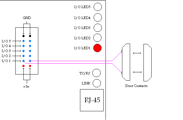

Figure 5

RMS
 
RMSv1 Hardware Screen Shot

RMSv1 Software Screen Shot
Download Software Here!


RMS
 

MRTG Scripts available

These real-time MRTG samples are updated every five minutes!

Main Battery Power on Apex Mountain

The graph above depicts main battery power at our wireless internet repeater site on Apex Mountain. Bumps in the graph represent charging from either solar panels or an Air403 wind turbine. Supplementary power is provided by a Honda Generator that is remote started with RMSv1. The 24v battery bank is monitored by RMSv1 and polled every five minutes. This provides a quick and easy way to check battery levels at anytime from anywhere a web browser is available!

Temperature Monitor on Apex Mountain

The graph above depicts room temperature at our wireless internet repeater site on Apex Mountain. Dips or bumps in the graph represent temperature changes. The temperature of our equipment room is monitored by RMSv1 and polled every five minutes. This provides a quick and easy way to check temperature at anytime from anywhere a web browser is available!

Main Battery Power on Hedley Mountain

The graph above depicts main battery power at our wireless internet repeater site on Hedley Mountain. Bumps in the graph represent charging from either solar panels or an Air403 wind turbine. Supplementary power is provided by a Honda Generator that is remote started with RMSv1. The 12v battery bank is monitored by RMSv1 and polled every five minutes. This provides a quick and easy way to check battery levels at anytime from anywhere a web browser is available!

Temperature Monitor on Hedley Mountain

The graph above depicts room temperature at our wireless internet repeater site on Hedley Mountain. Dips or bumps in the graph represent temperature changes. The temperature of our equipment room is monitored by RMSv1 and polled every five minutes. This provides a quick and easy way to check temperature at anytime from anywhere a web browser is available!

RMS
 

For further information, technical questions or to purchase equipment please choose from the following:

Contact:

In Canada & Overseas

EtherTek Circuits
Dan Pattison
Phone (250)295-6794

In the United States

Invictus Networks LLC
Rick Lindahl
Phone: 503-635-2562,
Fax: 503-635-9207


RMS