Powering up the GPS Monitor
The Network Enabled GPS Monitor is powered through its ethernet port with passive POE. Included with each GPS monitor is a passive POE injector, 24vdc power supply, and external antenna. To get started, attach the external antenna connector to the GPS Monitor device. Put the antenna block outside or near a window so that it has good visibility to the sky. Plug the power supply into a wall outlet. The round barrel jack on the power supply plugs into the mating connector on the passive POE injector. The short Cat5 cable on the POE injector plugs into your computer, router, or switch. Use a standard Cat5 cable of the proper length and plug one end into the POE injector, plug the other end into the GPS Monitor. The Network Enabled GPS Monitor should now be powered up. When powered properly, the RED power led on the GPS Monitor will be on, and the green FIX led will start blinking. The Green FIX led will be on solid when a satellite fix is established. You should also see the network leds located on the RJ-45 jack start to blink indicating a network connection.
Note: You may at anytime restore the GPS Monitor device to factory default values
by pressing and holding down the micro push button located inside the enclosure near the
RJ-45 connector and then plugging in the POE network cable. Release the button when the
status led stops its fast pulse (5 seconds).
Logging in to the GPS Monitor
We recommend configuring the GPS Monitor before deploying it in the field. When the GPS
Monitor is powered up it boots the operating system and uses the values stored on its
internal flash to bring up the system. The default values consist of an IP address,
username, and password. The default IP address is 10.10.10.222. The default username is
root. The default password is pass. Plug the short Cat5 cable from the POE injector into
your computer. Give your computer an ip address in the 10.10.10.X class. For instance use
10.10.10.1. Set your computers Netmask to 255.255.255.0 There is no need to set a Gateway
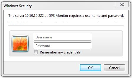
at this time. Open your favorite web browser and enter 10.10.10.222 into the address bar,
press enter or click the go button. You should be presented with a password box similar to
the one below.
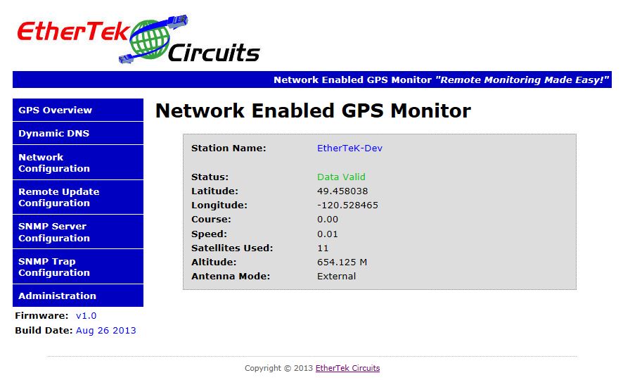
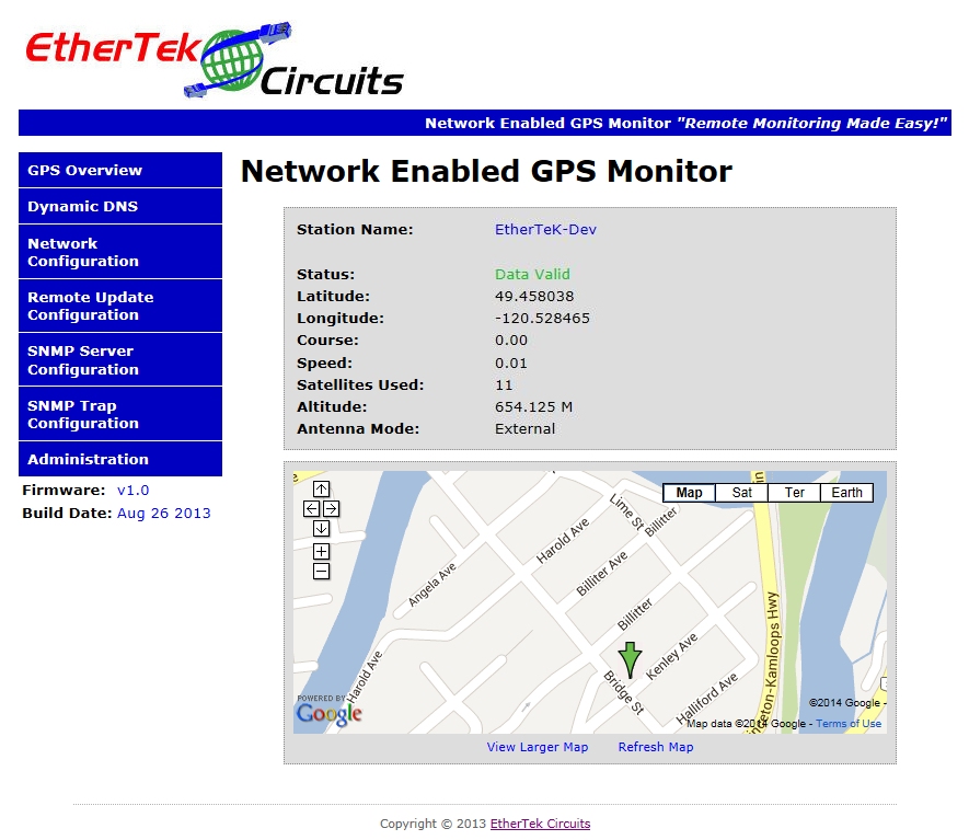
The Overview Page
Below is a screen shot of the GPS Overview page. The overview page displays information about this GPS Monitor device such as station name, GPS coordinates, course, speed, satellites used, altitude, and antenna mode. If an Internet connection is available a map may also be displayed on the Overview page that shows a marker of the current GPS coordinates. The map is turned ON or OFF in the Administration area.
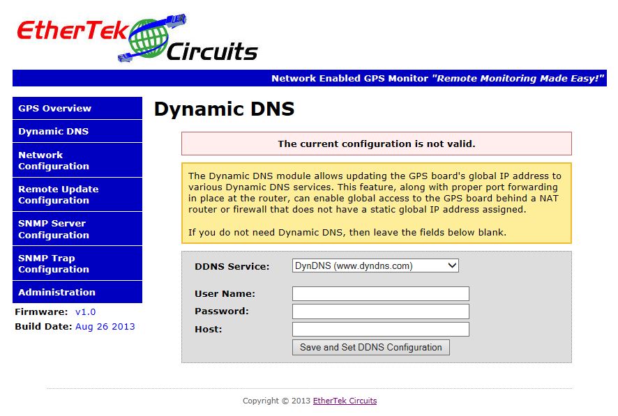
The Dynamic DNS Page
Below is a screen shot of the Dynamic DNS setup page. The Dynamic DNS module allows updating the GPS board's global IP address to various Dynamic DNS services. This feature, along with proper port forwarding in place at the router, can enable global access to the GPS board behind a NAT router or firewall that does not have a static global IP address assigned.
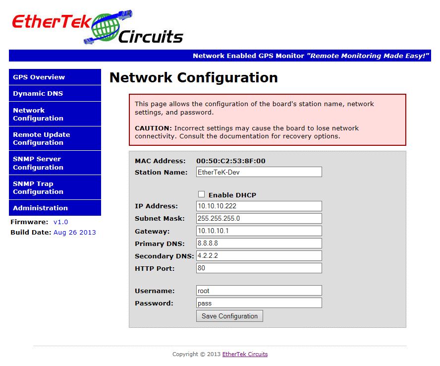
The Network Configuration Page
Below is a screen shot of the Network setup page. This page allows the configuration of the board's station name, network settings, and password. By default the Network GPS board is set with a static IP address of 10.10.10.222 with the http port set at 80. The NGPS board can be set to obtain an IP address automatically using DHCP. When DHCP is enabled, find the NGPS board in your web browser with http://ethertek-gps/
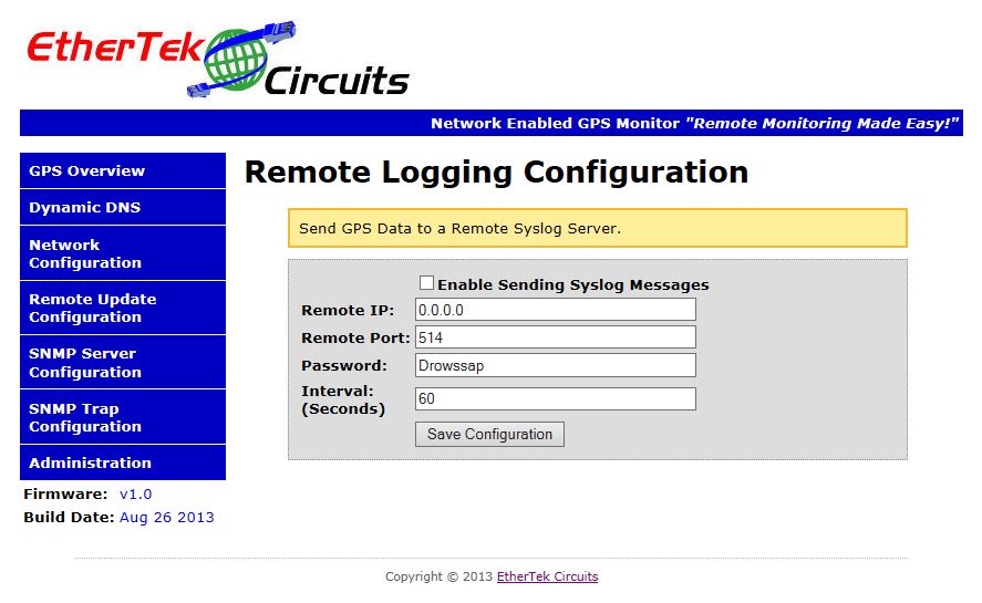
The Remote Update Configuration Page
Below is a screen shot of the Remote Update setup page. This page allows the configuration
of where to send GPS data to a Remote Syslog Server. A Remote Syslog Server can be setup in
your Network Operations Center to receive and parse GPS data messages and display that on a
map overlay. Set the remote IP Address of your Remote Syslog Server, the remote port, the
password, and Interval. The syslog message payload is broken into parts by a pipe |
character. The data format of the remote syslog message is below.
Station Name | Data Vaid or not | Longitude | Latitude | Course | Speed | Satellites Used |
Altitude in Meters | Antenna Mode
An example syslog message:
EtherTeK-Dev|Data Valid|49.458038|-120.528465|0.02|197.22|8|635.515 M|External
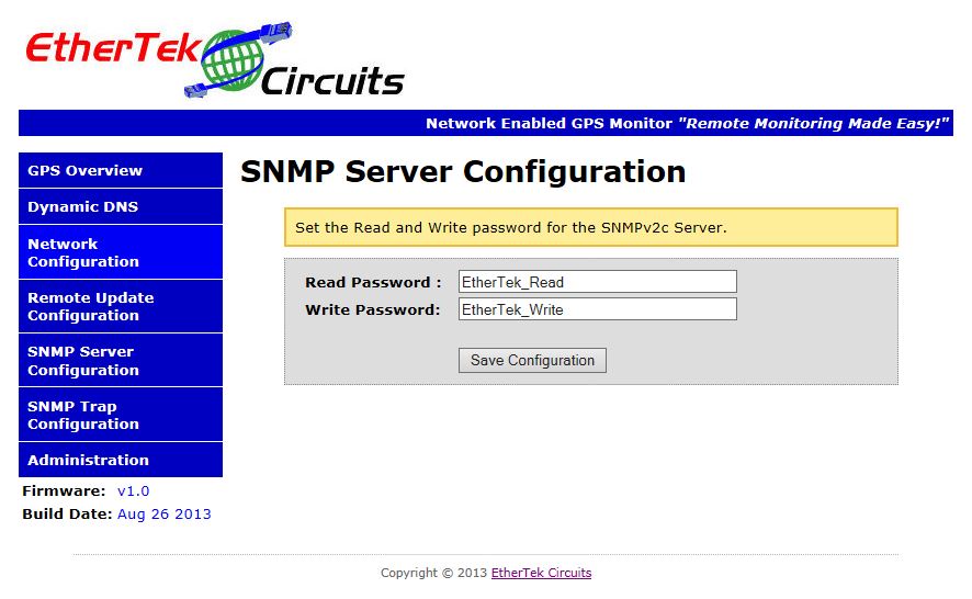
The SNMP Server Configuration Page
Below is a screen shot of the SNMP Server setup page. This page allows you to set the read and write password for the SNMPv1/2 server. The SNMP server listens on port 161 for SNMP queries. All GPS data can be pulled from the NGPS board via SNMP. Look at the EtherTek MIB file for the specific OIDS used to obtain data.
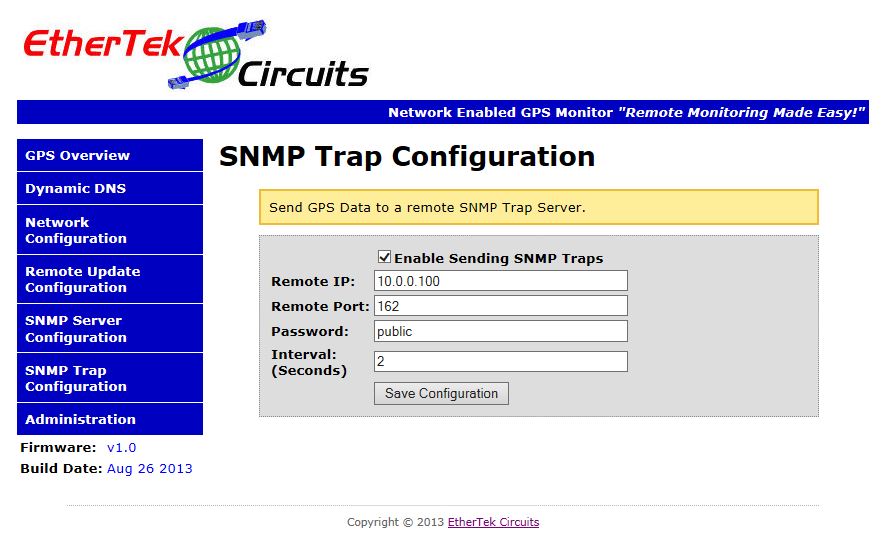
The SNMP Trap Configuration Page
Below is a screen shot of the SNMP Trap setup page. This page allows the configuration of
where to send GPS data to a remote SNMP Trap server. A remote SNMP Trap server can be setup
in your Network Operations Center to receive and parse GPS data messages and display that
on a map overlay. Set the remote IP Address of your SNMP Trap server, the remote port, the
password, and Interval. The SNMP Trap message payload is broken into parts by a pipe |
character. The data format of the SNMP Trap message is below.
Station Name | Data Vaid or not| Longitude | Latitude | Course | Speed | Satellites Used |
Altitude in Meters | Antenna Mode
An example SNMP Trap message:
EtherTeK-Dev|Data Valid|49.458038|-120.528465|0.02|197.22|8|635.515 M|External
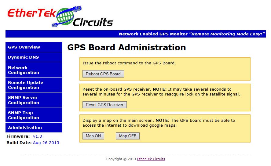
The Administration Setup Page
Below is a screen shot of the Administration setup page. This page allows you to reboot the NGPS board, issue a reset command to the GPS chip, or show the map on the NGPS overview page.
The Overview Page with Map enabled
Below is a screen shot of the Overview page with the map enabled. The NGPS board must have internet access to display map data.
Pulling Data from the Network GPS board
Data can be pulled from the GPS board by directly calling certain URL's. Below is a list of URL's and example output.
All Of It URL Example with JSON format:
http://10.10.10.222/server/allofit-json.cgi
Output:
{"station_name":"EtherTeK-Dev","gpsstatus":"Data Valid","latitude":"49.458019",
"longitude":"-120.528450","course":"237.19","speed":"0.03","satsused":"13","altitude":"650.060 M",
"antennamode":"External"}
All Of It URL Example with JSONP format:
http://10.10.10.222/server/allofit-jsonp.cgi
Output:
allofit({"station_name":"EtherTeK-Dev","gpsstatus":"Data Valid","latitude":"49.458019",
"longitude":"-120.528450","course":"237.19","speed":"0.03","satsused":"13","altitude":"650.060 M",
"antennamode":"External"});
All Of It URL Example with PIPE format:
http://10.10.10.222/server/allofit-pipe.cgi
Output:
EtherTeK-Dev|Data Valid|49.458019|-120.528450|237.19|0.01|11|650.409 M|External
Altitude URL Example:
http://10.10.10.222/server/altitude.cgi
Output:
653.289 M
Antenna Mode URL Example:
http://10.10.10.222/server/antennamode.cgi
Output:
External
Course URL Example:
http://10.10.10.222/server/course.cgi
Output:
233.91
GPS Status URL Example:
http://10.10.10.222/server/gps_status.cgi
Output:
Data Valid
Latitude URL Example:
http://10.10.10.222/server/latitude.cgi
Output:
49.558019
Longitude URL Example:
http://10.10.10.222/server/longitude.cgi
Output:
-120.428450
Satellites Used URL Example:
http://10.10.10.222/server/satsused.cgi
Output:
8
Speed URL Example:
http://10.10.10.222/server/speed.cgi
Output:
0.01
Station Name URL Example:
http://10.10.10.222/server/station_name.cgi
Output:
EtherTeK-Dev
Our Story
EtherTek Circuits started its business in 2001. Ever since we have provided remote monitoring and control solutions for Remote Tower Sites, the Oil & Gas industry, Telemetry systems for Agriculture, Municipalities, Mines, Solar Farms, Hydro Plants, and the Military.


